6. Wavelength Calibration Guide for GNIRS XD
The wavelength calibration for GNIRS XD can be quite involved depending on the instrument configuration, in particular the resolution used and the central wavelength setting.
The telluric modeling depends critically on the wavelength solution, so it very important to get it right and invest the time needed to do it properly.
At this time, the DRAGONS software measures the wavelength solution independently for each order, which means that it is not uncommon to have some orders with poor line coverage, whether it be arc lines, sky emission lines or telluric features. This will remain a problem until the DRAGONS team can implement a 2-D wavelength calibration solution.
This guide will help you figure out the most likely approach you will need. Especially in the high resolution mode, 111l/mm grating, a combination of solution methods is often needed.
We have not tested all the configuration. The table below is based on limited experimentation and it is meant as a guide, not as a set of absolute rules. The table covers the most commonly used configurations. We will add more configurations as we study them.
Camera |
Grating |
Central |
Advise |
Short Blue |
32/mm |
~1.65 |
most likely: The arcs will normally have enough lines and |
111/mm |
H-band range |
most likely: You will need a combination of methods and |
|
Long Blue |
10/mm |
~1.65 |
most likely: The arcs will normally have enough lines and |
 m
m6.1. Usage
6.1.1. Need for a processed flat
Even when you are reducing an arc lamp observation, a flat is required to get the slit model. The data will not be flat fielded, but the slit model in the processed flat will be used to defined the edges of each order. It will be picked up automatically by the calibration manager.
6.1.2. Wavelength calibration methods
6.1.2.1. From the Arc Lamp
Producing a wavelength solution from the arc observations is fairly straightforward. Just call reduce on the raw arcs.
The use of the interactive mode is recommended to verify the solution and ensure that the lines offer a good coverage the entire spectral range, across the six orders. If any order has too few lines, consider using the sky lines solution.
reduce @arcs.lis -p interactive=True
6.1.2.2. From the Sky Emission Lines
When OH and O2 lines are present in the science data, it is possible to use those to calculate the wavelength solution. Often the number of lines and the coverage will be better than what the arc lamp can provide, at least for orders 3 to 6, if using the 111/mm grating.
The sky lines will be fewer or fainter in orders 7 and 8.
The wavelength calibration is obtained from the sky lines by running
reduce on the science frames and specifying the use of the
makeWavecalFromSkyEmission recipe. The interactive mode is
recommended to verify and ensure correct line identification and to inspect
which orders might have a poor solution requiring a different approach.
reduce @sci.lis -r makeWavecalFromSkyEmission -p interactive=True
If the OH and O2 sky lines are bright, it is possible to use only one science observation instead of the stack. This could lead to higher precision as the stack might make the lines a touch thicker.
6.1.2.3. From the Telluric Absorption Features
When the arc lamp offers very few lines, or poor coverage (eg. all the lines at one end of the spectrum), and there are no emission lines, one has to resort to using the telluric absorption features to measure the wavelength solution.
This is done by running reduce on the science frames and specifying the use
of the makeWavecalFromSkyAbsorption recipe.
This recipe benefits from a solution from the arc lamp to serve as initial condition. So in this case, there are two steps to the process.
reduce @arcs.lis -p interactive=True
caldb remove N20210407S0181_arc.fits

reduce @sci.lis -r makeWavecalFromSkyAbsorption --user_cal processed_arc:N20210407S0181_arc.fits -p interactive=True
If we resort to the telluric method, it is because the arc solution is poor. So we remove it from the calibration manager to ensure that no science reduction uses it. Note that the telluric might also be poor for some orders, so it is likely that you will end up combining solutions from different methods.
The interactive mode is highly recommended to verify and ensure correct line identification.
6.1.2.4. Combining Wavelength Solutions
As shown in Example 2, when a single method does not provide a good solution we need to combine orders from wavelength solutions obtained with different methods.
This is done with with the recipe combineWavelengthSolutions, followed
by the primitive storeProcessedArc to add the new combined solution to the
calibration database. For example:
reduce -r combineWavelengthSolutions N20191013S0006_arc.fits N20191013S0034_arc.fits -p ids=1,2,3,6
reduce -r storeProcessedArc N20191013S0006_combinedArc.fits -p suffix=_arc155
Important
The primitive used by the recipe to combineSlices is
generic, which means that it knows about extensions, not about “Orders”.
The Orders 3 to 8 are stored in extensions 1 to 6, respectively.
This is the index scale we have to use. It is not the most elegant
solution, but for now, it works.
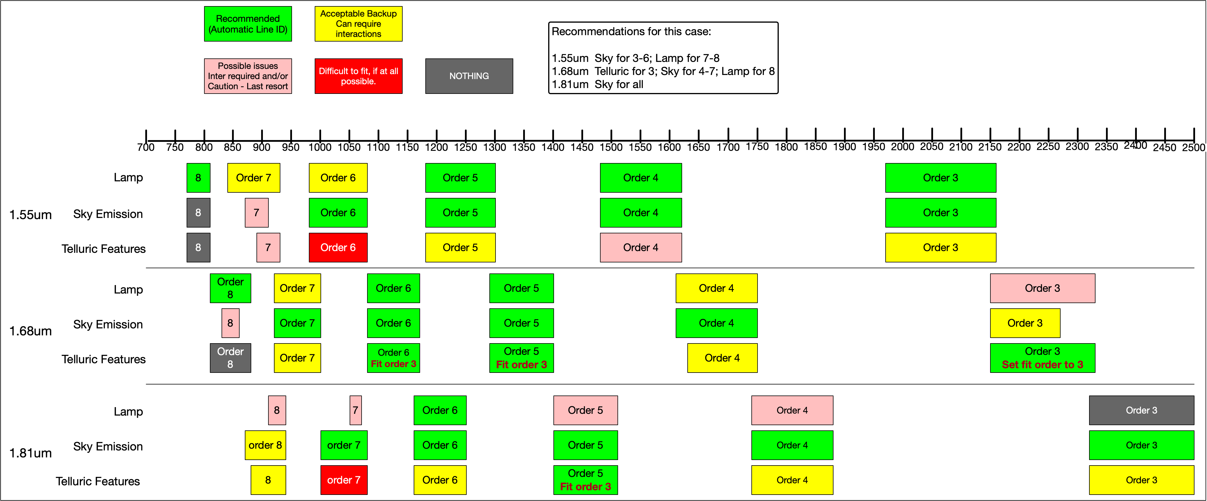
6.1.3. Special Considerations for the 111/mm Grating
The each order when the 111/mm grating is used covers a very small wavelength range. This means that the number of arc lines per order is going to be small. Also, because the specific region depends on the central wavelength selected, predicting the quality of the wavelength calibration one is going to obtain is difficult.
We have also found that just evaluating the wavelength calibration based
on the determineWavelengthSolution plots is not sufficient. We tried
as illustrated in the diagram below. Then, when we ran fitTelluric
(see Example 2) we found that there are exception.
Therefore, use the diagram as a first guide, but always verify the adequacy
of the solution using fitTelluric as shown in Example 2.
Keep in mind that the diagram applies only for those specific central wavelengths.
As a general recommendation, avoid using the telluric line solution if there is another method that leads to reasonable results.